
MOTORCYCLE ECU FILE LIBRARY
XDF Files
Find the right definition for your next tune.
Find your ECU file

ECU Definition Preview
Yamaha YZF-R1 2009-2011

45B-8591A-10 01
| ECU P/N | 45B-8591A-10 01 |
|---|---|
| Calibration ID | G705YSF2 |
| Model years | 2009-2011 |
| Compatible BIN size | 512 KB (524,288 bytes) |
€70.00
You receive: XDF definition for TunerPro
File reference & categories
Description
This XDF definition for Yamaha YZF-R1 2009-2011.
Calibration ID: G705YSF2
ECU part number: 45B-8591A-10 01
to check for an exact reference match before choosing a definition.
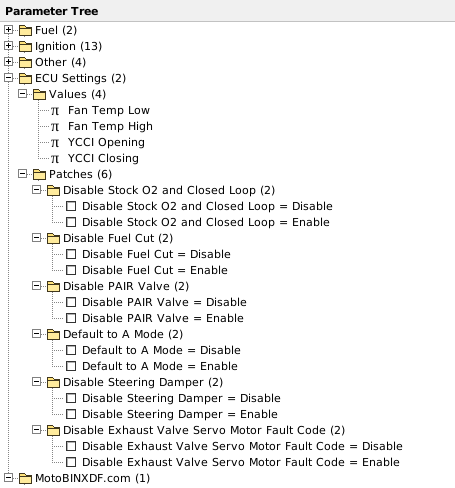
ECU Settings — Patches & Values
Options included in this XDF definition.
Patches & switches
- Disable Stock O2 and Closed Loop
- Disable Fuel Cut
- Disable PAIR Valve
- Default to A Mode
- Disable Steering Damper
- Disable Exhaust Valve Servo Motor Fault Code
Adjustable values & tables
- Fan Temp Low
- Fan Temp High
- YCCI Opening
- YCCI Closing
ECU Definition Preview
Fuel
IAP
- IAP / Cyl 1 (50×50)
- IAP / Cyl 2 (50×50)
- IAP / Cyl 3 (50×50)
- IAP / Cyl 4 (50×50)
TPS
- TPS / Cyl 1 (50×50)
- TPS / Cyl 2 (50×50)
- TPS / Cyl 3 (50×50)
- TPS / Cyl 4 (50×50)
Ignition
- Ignition / Gear 0 (36×23)
- Ignition / Map 1 (36×23)
- Ignition / Map 2 (36×23)
- Ignition / Map 3 (36×23)
- Ignition / Map 4 (36×23)
- Ignition / Map 5 (36×23)
- Ignition / Map 6 (36×23)
- Ignition / Map 7 (36×23)
- Ignition / Map 8 (36×23)
- Ignition / Map 9 (36×23)
- Ignition / Map 10 (36×23)
- Ignition / Map 11 (36×23)
- Ignition / Map 12 (36×23)
Other
Upper Injector Balance
- Upper Injector Balance (15×14)
Fuel Injector Timing
- Fuel Injector Timing / Primary Injector (17×10)
- Fuel Injector Timing / Secondary Injector (17×10)
Coolant Temperature Idle Compensation
- Coolant Temperature Idle Compensation (10×15)
Ignition Dwell
- Ignition Dwell (18×9)
ECU Settings
Values
- Fan Temp Low
- Fan Temp High
- YCCI Opening
- YCCI Closing
Patches
Disable Stock O2 and Closed Loop
- Disable Stock O2 and Closed Loop = Disable
- Disable Stock O2 and Closed Loop = Enable
Disable Fuel Cut
- Disable Fuel Cut = Disable
- Disable Fuel Cut = Enable
Disable PAIR Valve
- Disable PAIR Valve = Disable
- Disable PAIR Valve = Enable
Default to A Mode
- Default to A Mode = Disable
- Default to A Mode = Enable
Disable Steering Damper
- Disable Steering Damper = Disable
- Disable Steering Damper = Enable
Disable Exhaust Valve Servo Motor Fault Code
- Disable Exhaust Valve Servo Motor Fault Code = Disable
- Disable Exhaust Valve Servo Motor Fault Code = Enable
MotoBINXDF.com
- Definition information
View all maps & axes 26 tables
Table names, dimensions and units from this XDF.
| Map / group | Size | X axis / unit | Y axis / unit | Value unit |
|---|---|---|---|---|
| IAP / Cyl 1Fuel / IAP | 50 × 50 | IAP (Inlet/Manifold Absolute Pressure) = cm Hg | RPM = | — |
| IAP / Cyl 2Fuel / IAP | 50 × 50 | IAP (Inlet/Manifold Absolute Pressure) = cm Hg | RPM = | — |
| IAP / Cyl 3Fuel / IAP | 50 × 50 | IAP (Inlet/Manifold Absolute Pressure) = cm Hg | RPM = | — |
| IAP / Cyl 4Fuel / IAP | 50 × 50 | IAP (Inlet/Manifold Absolute Pressure) = cm Hg | RPM = | — |
| TPS / Cyl 1Fuel / TPS | 50 × 50 | TPS (Throttle Position Sensor) = % | RPM = | — |
| TPS / Cyl 2Fuel / TPS | 50 × 50 | TPS (Throttle Position Sensor) = % | RPM = | — |
| TPS / Cyl 3Fuel / TPS | 50 × 50 | TPS (Throttle Position Sensor) = % | RPM = | — |
| TPS / Cyl 4Fuel / TPS | 50 × 50 | TPS (Throttle Position Sensor) = % | RPM = | — |
| Ignition / Gear 0Ignition | 36 × 23 | TPS (Throttle Position Sensor) = % | RPM = | — |
| Ignition / Map 1Ignition | 36 × 23 | TPS (Throttle Position Sensor) = % | RPM = | — |
| Ignition / Map 2Ignition | 36 × 23 | TPS (Throttle Position Sensor) = % | RPM = | — |
| Ignition / Map 3Ignition | 36 × 23 | TPS (Throttle Position Sensor) = % | RPM = | — |
| Ignition / Map 4Ignition | 36 × 23 | TPS (Throttle Position Sensor) = % | RPM = | — |
| Ignition / Map 5Ignition | 36 × 23 | TPS (Throttle Position Sensor) = % | RPM = | — |
| Ignition / Map 6Ignition | 36 × 23 | TPS (Throttle Position Sensor) = % | RPM = | — |
| Ignition / Map 7Ignition | 36 × 23 | TPS (Throttle Position Sensor) = % | RPM = | — |
| Ignition / Map 8Ignition | 36 × 23 | TPS (Throttle Position Sensor) = % | RPM = | — |
| Ignition / Map 9Ignition | 36 × 23 | TPS (Throttle Position Sensor) = % | RPM = | — |
| Ignition / Map 10Ignition | 36 × 23 | TPS (Throttle Position Sensor) = % | RPM = | — |
| Ignition / Map 11Ignition | 36 × 23 | TPS (Throttle Position Sensor) = % | RPM = | — |
| Ignition / Map 12Ignition | 36 × 23 | TPS (Throttle Position Sensor) = % | RPM = | — |
| Upper Injector BalanceOther / Upper Injector Balance | 15 × 14 | TPS (Throttle Position Sensor) = % | RPM = | — |
| Fuel Injector Timing / Primary InjectorOther / Fuel Injector Timing | 17 × 10 | TPS (Throttle Position Sensor) = % | RPM = | — |
| Fuel Injector Timing / Secondary InjectorOther / Fuel Injector Timing | 17 × 10 | TPS (Throttle Position Sensor) = % | RPM = | — |
| Coolant Temperature Idle CompensationOther / Coolant Temperature Idle Compensation | 10 × 15 | Coolant Temperature = 'C | RPM = | — |
| Ignition DwellOther / Ignition Dwell | 18 × 9 | Voltage = v | RPM = | — |
Related files



Contact Us
Need help with a file, payment or download? Send a message to [email protected].
File Request
Can't find the BIN or XDF you need? Tell us about your ECU and the file you are looking for.
A file request does not create an order or charge your card. Any attached BIN is handled privately and is never published or executed.
YOUR MOTOBINXDF ACCOUNT
My Account
Manage your details, orders and downloads.
Loading your account…
Help
How do I find the right file?+
Choose BIN Files or XDF Files, then manufacturer, model and year. You can also search by ECU part number or calibration ID. Check the exact software reference on the product page.
How does BIN identification work?+
Your browser calculates the file fingerprint and sends only that fingerprint and its size for comparison. The BIN stays on your device. Only an exact reference match returns linked definitions. Modified or unknown files may not match.
What are BIN and XDF files?+
A BIN contains ECU binary data. An XDF describes the maps and settings for compatible software such as TunerPro. The definition must match the ECU software.
Which TunerPro version should I use?+
For XDF patch operations, use TunerPro 5.00.10305. Our tests found that TunerPro 6.0.496.0 can read patch data incorrectly after reopening a definition. Always edit a copy of your original BIN.
How can I purchase a file?+
Prices are in EUR. Add a file to your cart and pay securely with PayPal. You can check out as a guest. Download links are sent to your PayPal email address; your checkout shows the download limits before you pay. Sign in to My Account to view your orders and eligible account discounts. For enquiries, contact [email protected].
How can I request a file?+
Use File Request to email us directly from the website. Include the model, year, ECU part number and calibration ID. You can attach a reference BIN up to 16 MiB.